
We’ve covered CNMG120412 (negative diamond) and WNMG080412 (negative trigon). Now let’s decode CCMT09 — a positive insert with a completely different clearance angle, meaning different cutting behavior entirely.
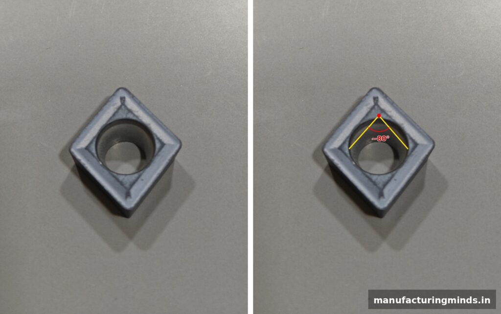
C — Shape: 80° Rhombic
Same diamond shape as our CNMG insert — “C” indicates an 80° rhombic geometry, marked below.
C — Clearance Angle: 7° (Positive Insert)
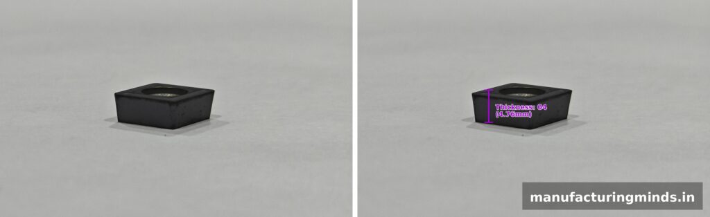
Here’s where CCMT09 differs fundamentally from our previous two inserts. The second letter “C” means a 7° clearance angle — a positive insert. Unlike the perfectly vertical wall of a negative insert, you can actually see the wall lean inward toward the top in the photo below — measured directly from this image, that taper works out to almost exactly 7°, matching the spec.
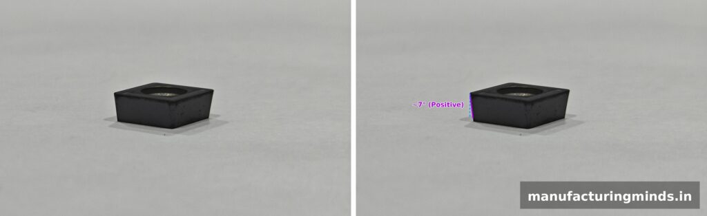
(practical implication):
This angled geometry means only one face of the insert is usable (unlike negative inserts' two faces), but it cuts with less force and a sharper edge — ideal for thin-walled parts, softer materials, and finishing passes where minimizing deflection matters more than maximizing edge count.
M — Tolerance Class M
Same as our previous two inserts — “M” specifies a standard tolerance class, providing consistent, general-purpose dimensional precision. No photo needed here since tolerance class isn’t something you can visually distinguish by eye.
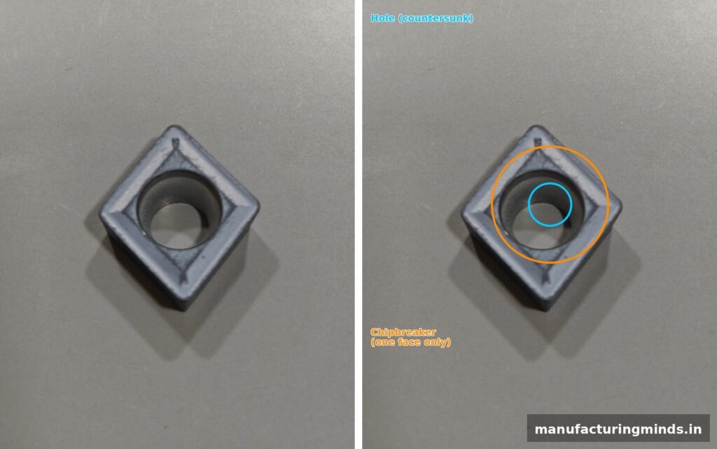
T — Without Hole, Chipbreaker on One Face
Unlike “G” (hole + chipbreaker on both faces), “T” means this insert has no center hole and a chipbreaker groove on only one face. Positive inserts like this are often held in the toolholder by a top clamp rather than a center screw — since there’s no hole, you’ll only find the chipbreaker molded into a single usable face, matching the fact that positive inserts only use one face anyway.
09-04-04 — Size, Thickness, Corner Radius:
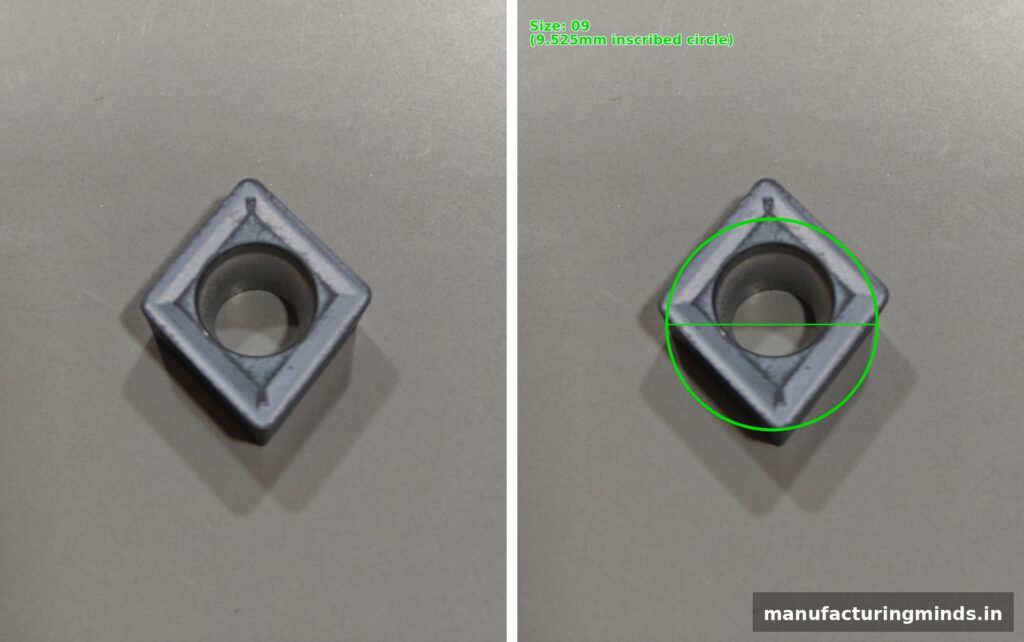
09 — Size (Inscribed Circle)
The size code “09” refers to the inscribed circle diameter — 9.525mm (3/8″) for this insert, matching the same size class as our WNMG080412 example.
04 — Thickness
The next pair, “04,” specifies the thickness — 4.76mm from top face to bottom face, the same as our CNMG120412 and WNMG080412 examples.
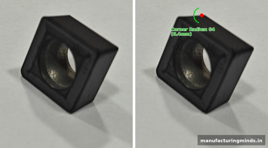
04 — Corner Radius
The final pair, “04,” specifies the corner radius — 0.4mm in this case, notably smaller than the 1.2mm radius on our CNMG and WNMG examples. A smaller radius creates a sharper point, better suited for fine-detail work and tight-radius profiles, but with less strength at the tip compared to a larger radius — an important trade-off to consider when choosing between insert families.
Coming Up Next
We’ve now covered three fundamental insert types — CNMG120412 (negative diamond), WNMG080412 (negative trigon), and CCMT090404 (positive diamond). Together, these cover the majority of general-purpose external turning scenarios you’ll encounter on the shop floor. In our next article, we’ll bring these together with a practical comparison guide — when to choose which insert, and why.
© 2026 Manufacturing Minds Precision LLP. All rights reserved. This content may not be reproduced without permission.
1 thought on “Understanding ISO Turning Insert Designation: CCMT09… Explained”