
In our previous article, we broke down CNMG120412 — a diamond-shaped negative insert. This time, we’re decoding WNMG080412, a trigon-shaped insert with a different geometry and trade-offs. Same method: real photos, position by position.
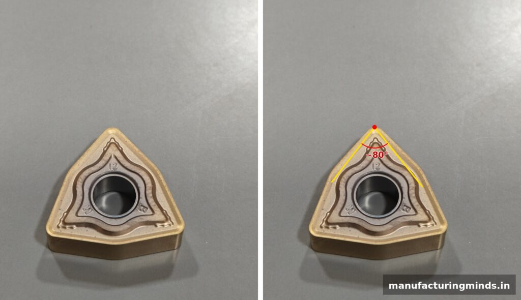
W — Shape: Trigon (80° Included Angle)
The first letter, “W,” indicates a trigon shape — a three-sided insert with an 80° included angle at each tip, shown marked below. Unlike the diamond-shaped CNMG insert (2 usable edges), a trigon gives you three cutting edges per insert, which can reduce tooling cost over high-volume runs.
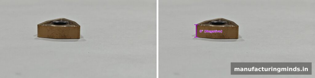
N — Clearance Angle: 0° (Negative Insert)
Just like our CNMG120412 insert, the second letter “N” means this is a negative insert with a 0° clearance angle. The side wall sits perfectly vertical, meaning both the top and bottom faces can be used as cutting surfaces — combined with the trigon shape’s three edges, this gives you six total usable cutting edges from one insert.
M — Tolerance Class M
Just like our CNMG120412 insert, the third letter “M” specifies a standard tolerance class — consistent, general-purpose dimensional precision suitable for everyday turning operations.
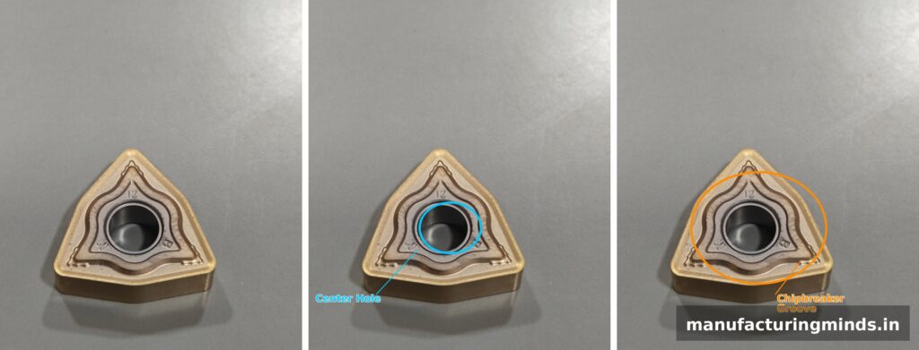
G — With Hole, Chipbreaker on Both Faces
Same combined designation as CNMG120412 — “G” means a cylindrical hole for clamping, paired with a chipbreaker groove molded on both faces. Below, the same insert shown as-is, with the center hole marked, and with the chipbreaker groove marked.
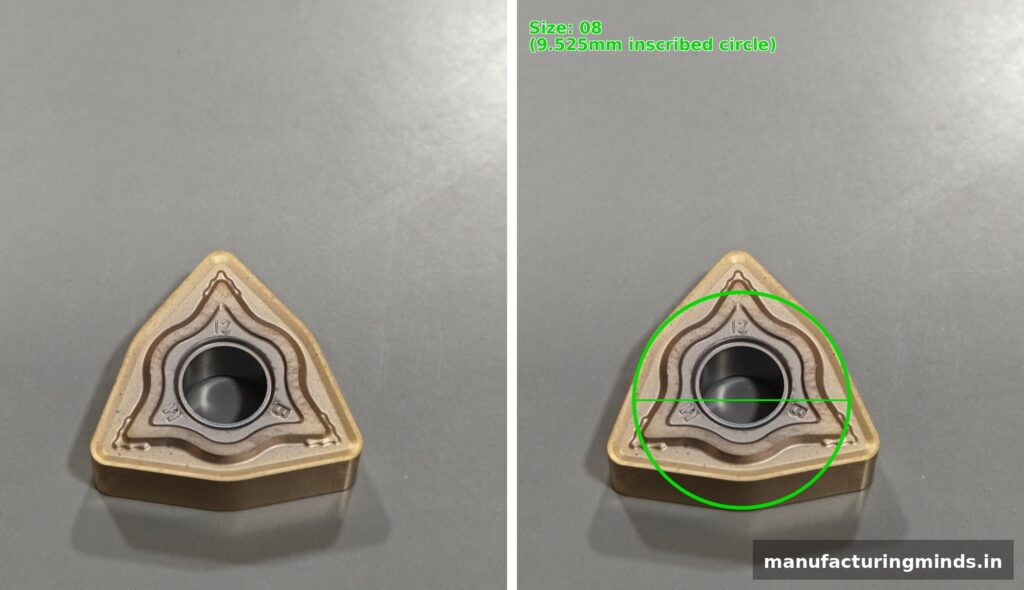
08-04-12 — Size, Thickness, and Corner Radius
The first pair, “08,” refers to the inscribed circle size — 9.525mm (3/8″) in this case. As with our CNMG article, remember: this is the diameter of a circle touching all edges of the shape, not the length of a cutting edge itself.
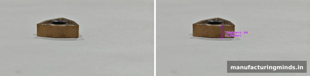
The second pair, “04,” specifies the thickness — 4.76mm from top face to bottom face, same as our CNMG120412 insert.
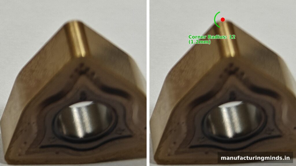
The final pair, “12,” specifies the corner radius — 1.2mm, visible in the close-up below.
Coming Up Next
We’ve now covered both CNMG120412 and WNMG080412 in detail. In our next article, we’ll break down CCMT09… — a positive insert with a completely different geometry. Stay tuned.
© 2026 Manufacturing Minds Precision LLP. All rights reserved. This content may not be reproduced without permission.
2 thoughts on “Understanding ISO Turning Insert Designation: WNMG080412 Explained”