
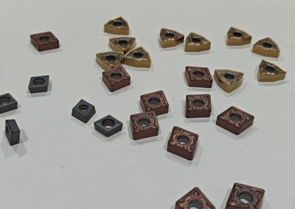
If you’ve ever picked up a box of carbide inserts and stared at a code like CNMG120412 wondering what it actually means, you’re not alone. The ISO 1832 standard gives every turning insert a code built from position-by-position rules shape, angle, tolerance, type, and size — all packed into 9-10 characters. Once you understand the system, you can read any insert code from any manufacturer and know exactly what you’re holding, without needing a catalog in hand.
In this article, we’ll break down three commonly used inserts — CNMG120412, WNMG080412, and CCMT09.— position by position, using real photos from our own tooling inventory.
How the ISO Code Is Structured
Every ISO insert code follows the same 10-position structure:
- Position 1: Insert Shape
- Position 2: Clearance (Relief) Angle
- Position 3: Tolerance Class
- Position 4: Insert Type (hole, chipbreaker style)
- Positions 5-6: Size (inscribed circle)
- Positions 7-8: Thickness
- Positions 9-10: Corner Radius
Decoding CNMG120412
Let’s break down our first insert, CNMG120412, position by position — with real photos from our own inventory.
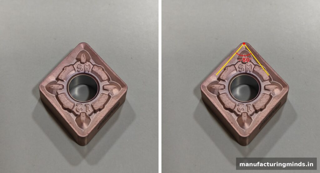
C — Shape: 80° Rhombic
The first letter defines the insert’s shape. “C” indicates an 80° rhombic (diamond) shape — a versatile, strong geometry commonly used for general-purpose external turning.
N — Clearance Angle: 0° (Negative Insert)
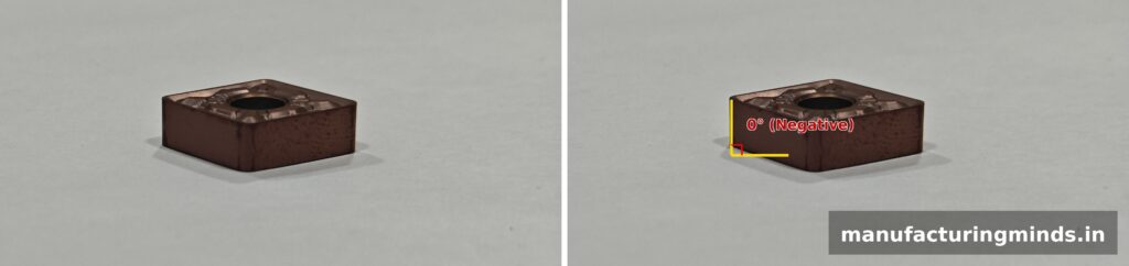
The second letter, “N,” means this insert has a 0° clearance angle — making it a negative insert. The side wall of a negative insert sits perfectly vertical (perpendicular to the top face), rather than angled inward like a positive insert. This flat wall means both the top and bottom faces can be used as cutting faces, effectively doubling the number of usable edges you get from a single insert.
M — Tolerance Class M
The third letter, “M,” specifies the insert’s tolerance class — essentially how tightly controlled the insert’s physical dimensions are during manufacturing. Tolerance class M is a widely used standard grade, offering good dimensional consistency suitable for general turning operations without requiring the tighter (and more expensive) tolerances found in precision-grade inserts.
G — With Hole, Chipbreaker on Both Faces
The fourth character, “G,” tells us this insert has a center hole and a molded chipbreaker groove on both faces. Below, the same insert is shown three ways — as-is, with the center hole marked, and with the chipbreaker groove marked.
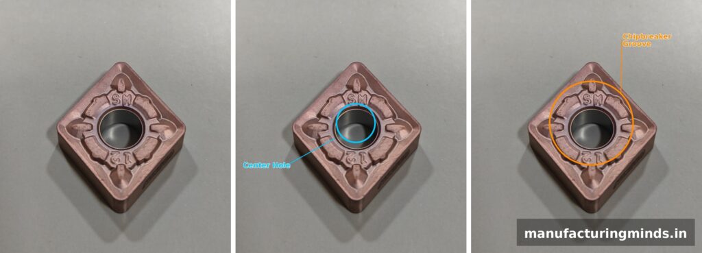
The fourth character isn’t just one feature — it’s a combined code representing both the hole type and the chipbreaker style together. “G” specifically means: a cylindrical hole (for clamping into the toolholder) combined with a chipbreaker groove molded on both the top and bottom faces. Manufacturers use a single letter here because hole style and chipbreaker style are standardized together as a pair, rather than specified as two separate codes.
12-04-12 — Size, Thickness, and Corner Radius
The final three number pairs specify the insert’s physical dimensions. The first pair, “12,” refers to the size — specifically, the diameter of a circle that would perfectly touch all four edges of the diamond shape, known as the inscribed circle. In this case, that’s 12.7mm (½ inch).
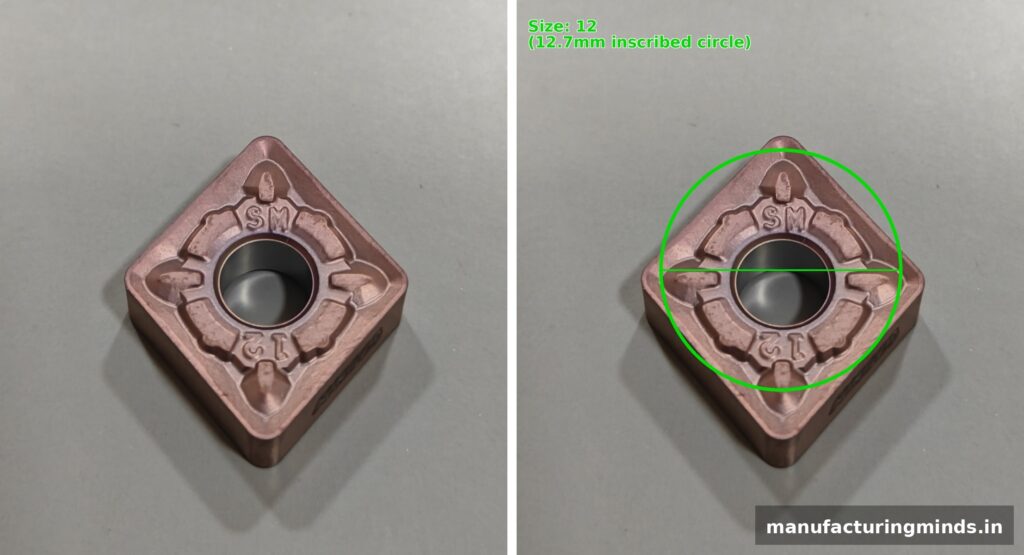
A common point of confusion: the size code refers to the inscribed circle diameter, not the length of the cutting edge itself. For a diamond-shaped insert like this one, the actual edge length is somewhat longer than the inscribed circle — the diamond’s sharp points extend beyond where the circle touches. This distinction matters most for square-shaped inserts, where the inscribed circle diameter and edge length happen to be equal.
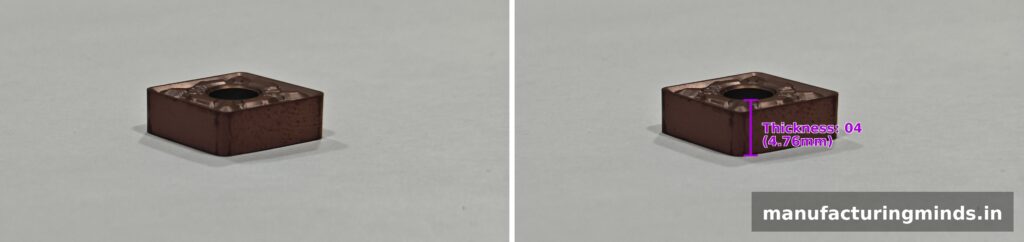
The second pair, “04,” specifies the insert’s thickness — the distance from the top face to the bottom face — which in this case is 4.76mm.
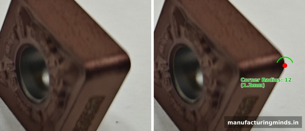
The last pair, “12,” specifies the corner radius — 1.2mm in this case. This is the curvature at each tip of the insert, visible in the close-up below.
Coming Up Next
We’ve covered CNMG120412 in full detail here. In our next article, we’ll break down WNMG080412 — the trigon-shaped insert — position by position, the same way, with real photos from our own tooling inventory. Stay tuned.
© 2026 Manufacturing Minds Precision LLP. All rights reserved. This content may not be reproduced without permission.
2 thoughts on “Understanding ISO Turning Insert Designation: CNMG, WNMG & CCMT Explained”